|
|
|
|
|
|
|
|

噪声分析的昨天与今天 Noise Analysis, Then and Today Dr. Ulrich L. Rohde Universität der Bundeswehr München, Munich, Germany 一直以来,人们都在尝试对振荡器这种自治电路进行噪声分析。David Leeson是第一个对此提出线性方法的人。他采用了线性低通等效电路,得出的线性公式1被后人反复引用。该公式所需的数据,要先通过post prior分析方可获得。输出功率、负载Q值、大信号噪声因子——常与噪声系数(NF)相混淆,后者可表示为10log(噪声因子)——及闪烁噪声贡献量均非先验值,尽管或许可以通过计算得出2。Hillbrand和Russer提出了分析节点噪声的恰当方法3。Lee-Hajimiri的噪声分析法2,4-6很新颖,却不怎么实用;虽然常被文献引用,但并没有体现出实际应用价值。如果我们将Leeson公式与调谐二极管贡献量结合在一起,便可得到下面这个公式,从而得以计算振荡器的完整噪声2。式中,Rohde2和Scherer7分别加入了VCO及闪烁噪声部分。
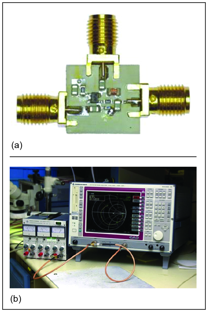
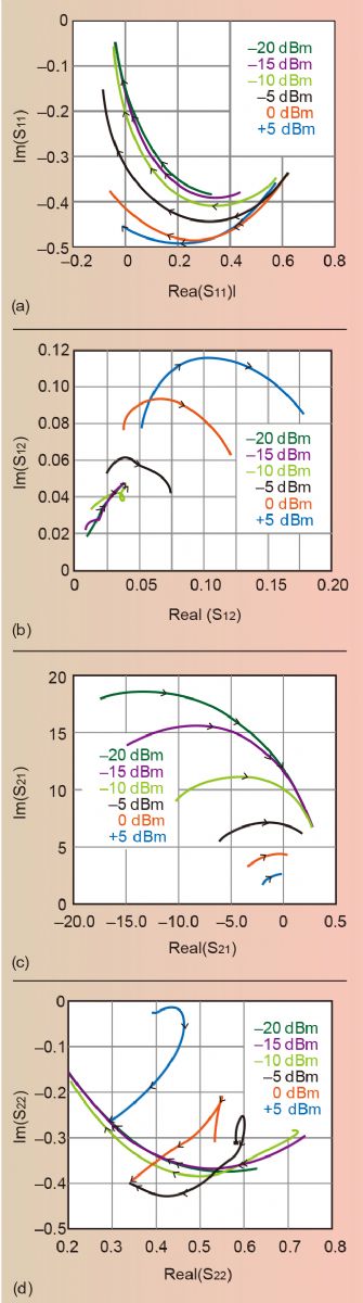
其中,L(fm)=1Hz带宽下fm时边带频率与总功率之比,单位dB;fm=频偏;f0=中心频率;fc=闪烁频率;QL=调谐电路的负载Q;F=噪声系数;kT=4.1×10⁻²¹,在300K0(室温);Psav=振荡器平均输出功率;R=调谐二极管等效噪声电阻(通常为50至10kΩ);Ko=振荡器电压增益。 Kaertner在论文中8采取了一个很好的时域法,或许是史上第一次提出了振荡器设计中的噪声相关关系。彼时,如今广为应用的谐波平衡法尚未问世。Rizzoli的文章9-11给出了到位的描述。Kaertner的计算过程虽然充斥着数学内容,较为晦涩,却得到了实际结果。 大信号噪声分析 由Vittorio Rizzoli及其团队开发的分段线性谐波平衡(HB)方法是包含噪声相关方法的完美体系。著名的非线性时域电路分析软件SPICE缺乏严格的噪声相关分析,而HB程序是线性(频率)和非线性(时域)计算的混合12,13。Rizzoli和Gilmore发表的文章都在引领这个话题。我在Compact Software工作期间曾与Rowan Gilmore共事。 我在Compact Software时带领的团队和Rizzoli团队都在争相努力验证结果,但想要保持准度和速度来获取可靠的测量数据较为复杂,两边一直在争论这个话题。我记得自己曾告诉用户,某些程序中使用的快捷方式只会让他们更快地得到错误答案。最终的解决方法是开发出一个快速双精度的多维矩阵求逆程序,采用Fortran能够得到最稳定的结果。这种HB法还能处理迟滞。 我们与Raytheon的Pucell及德州仪器的Tony Pavio14一起,发布了对于Raytheon研发的低噪声放大器所进行的首次也是最具挑战的电路分析。我们采用SPICE类型数据对GaAs FET呈现了精准结果。要取得这些数据很不容易,我们最终使用的是改进版的Materka模型15-19,实际电路发布在了《Microwave Journal》上20。目前,我已经向大家展示了GaAs FET及其它场效应管可通过使用准确的现成SPICE参数来进行噪声分析。 然而,真正需要大信号电路分析的是振荡器。选用合适的FET15-19和BJT20-22模型及衍生物是一项艰巨的任务。内部噪声建模基于噪声相关矩阵2,结果由W. Anzill、F.X.Caertner和P.Russer于1992年发表23。1987年,Compact Software的Microwave Harmonica程序经验证是可靠的20。下一步便是匹配实际电路的测量结果。第一个可靠的相位噪声系统属惠普公司所有;Dieter Scherer是其首席工程师。时至今日,领衔的相位噪声分析仪为Rohde & Schwarz的FSWP/8/26/50。 对于系统分析法而言,即使不采用仿真器,大信号S参数的作用也很大2,24。Kaertner发表论文时尚未得出双极晶体管的大信号参数,现在我们知道测量是最好的途径24。去嵌入操作19将外部测量值转换到实际芯片(图1a),其中测量过程中需要具备可变输出功率的网络分析仪(图1b)。BJT在大信号运行情况下与低噪声应用不同18-22,如图2所示25。
图1:用于测量大信号S参数的测试夹具(a),和网络分析仪(b)。
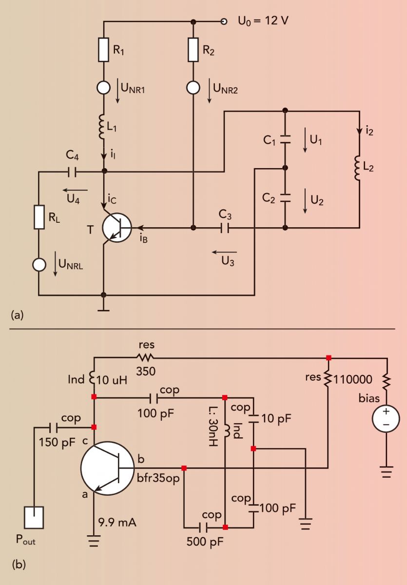
图2:Infineon的BFP520双极晶体管在600MHz至3GHz下以50MHz为单位,大信号S参数为:S11(a),S12(b),S21(c)和S22(d)。 KAERTNER COLPITTS振荡器 有了这些背景,我想进一步分析一下Kaertner在他那篇经典论文中用作基础的电路8,23。图3a原理图中的元件值取自他的文章:R1=350Ω,R2=110kΩ,RL=500Ω,L1=10μH,L2=30nH,C1=10pF,C2=940pF,C3=2.7nF,C4=1.5nF,T=BFR35A。
图3:Kaertner分析的Colpitts振荡器(a)、Compact Software中的电路原理图(b)。 Kaertner进行了一个电路理论中非同一般的简化:假设L2具备无穷大Q值。不过对于他的分析而言,由于电路实际上会加载无负载Q值,所以是允许的。电路具备无穷大Q值,C2=940pF,必然会振荡。若是采用实际Q值,如QL=100,那么C2的值必须减至100pF才能保证电路工作正常。同时,必须要提高反馈,把C4降低到100pF,因为不可能制造没有寄生电感的电容。同样的,10μH电感也最好调整至1μH,否则在工作频率下极有可能发生谐振。Kaertner4公布了他的振荡器计算得出的相位噪声,正确地指出其中不包括闪烁贡献量。 图3b表示了应用HB技术,使用Compact Software Microwave Harmonia建模时的Kaertner振荡器电路。仿真包括了闪烁噪声指数(AF)和闪烁噪声常数(KF),同时返回了结果,与Kaertner发表的相符(图4a)。AF和KF的影响在1kHz时清晰可见。仿真还预测了输出功率和谐波含量(图4b)。输出功率约为16dBm,谐波抑制约为20dB。这表明谐振电路的工作Q值良好。分析结果与性能表现吻合度极高。
图4:Kaertner振荡器的模拟相位噪声(a),和输出功率vs频率(b)。 小结 本文回顾了为准确预测放大器、倍频器和混频器中的大信号噪声,从而开发并验证一款通用非线性计算机辅助设计(CAD)工具的艰难历程。类似的例子还有很多2,14。 众人拾柴火焰高,整个过程得益于各位优秀人士的努力。Vittorio Rizzoli或许是其中贡献最大的一位;我带领的团队负责测试验证Serenade Harmonica程序,付出也不容小觑。之后,一种CAD独立数字时域计算工具得以问世,从此无需采用昂贵的器材,便可预测振荡器的噪声性能2,23-24。 参考文献 1. D. B. Leeson, “A Simple Model of Feedback Oscillator Noise Spectrum,” Proceedings of the IEEE, Vol. 54, No. 2, February 1966, pp. 329–330. 2. U. L. Rohde, A. K. Poddar and G. B.ck, The Design of Modern Microwave Oscillators for Wireless Applications: Theory and Optimization, pp. 131–137. 3. H. Hillbrand and P. Russer, “An Efficient Method for Computer Aided Noise Analysis of Linear Amplifier Networks,” IEEE Transactions on Circuits and Systems, Vol. 23, No. 4, April 1976. 4. L. A. Hajimiri, “Linearity, Time Variation, and Oscillator Phase Noise,” RF and Microwave Oscillator Design, Artech House, 2002. 5. A. Hajimiri and T. Lee, “A General Theory of Phase Noise in Electrical Oscillators,” IEEE Journal of Solid-State Circuits, Vol. 33, No. 2, February 1998, pp. 179–194. 6. D. Ham and A. Hajimiri, “Concepts and Methods in Optimization of Integrated LC VCOs,” IEEE Journal of Solid-State Circuits, June 2001. 7. D. Scherer, “Design Principles and Test Methods for Low Phase Noise RF and Microwave Sources,” RF and Microwave Measurement Symposium and Exhibition, Hewlett Packard, 1983. 8. F. X. Kaertner, “Determination of the Correlation Spectrum of Oscillators with Low Noise,” IEEE Transactions on Microwave Theory and Techniques, Vol. 37, No. 1, January 1989. 9. V. Rizzoli, F. Mastri and C. Cecchefti, “Computer-Aided Noise Analysis of MESFET and HEMT Mixers,” IEEE Transactions on Microwave Theory and Techniques, Vol. 37, September 1989, pp. 1401–1410. 10. V. Rizzoli and A. Lippadni, “Computer-Aided Noise Analysis of Linear Multiport Networks of Arbitrary Topology,” IEEE Transactions on Microwave Theory and Techniques, Vol. 33, December 1985, pp. 1507–1512. 11. V. Rizzoli, F. Mastri and D. Masotti, “General-Purpose Noise Analysis of Forced Nonlinear Microwave Circuits,” Military Microwave, 1992. 12. R. J. Gilmore and M. B. Steer, “Nonlinear Circuit Analysis Using the Method of Harmonic Balance—A Review of the Art. Part I. Introductory Concepts,” International Journal of Microwave and Millimeter-Wave Computer-Aided Engineering, Vol. 1, No. 1, January 1991, pp. 22–37. 13. R. J. Gilmore and M. B. Steer, “Nonlinear Circuit Analysis Using the Method of Harmonic Balance—A Review of the Art. Part II. Advanced Concepts,” International Journal of 367T. 14. U. L. Rohde and D. P. Newkirk, “RF/Microwave Circuit Design for Wireless Application,” Wiley, 2000. 15. R. A. Pucel, H. A. Haus and H. Statz, “Signal and Noise Properties of Gallium Arsenide Microwave Field-Effect Transistors,” Advances in Electronics and Electron Physics, Academic Press, Vol. 38, 1975. 16. U. L. Rohde, “New Nonlinear Noise Model for MESFETs Including MM-Wave Application,” First International Workshop of the West German IEEE MTT/AP Joint Chapter on Integrated Nonlinear Microwave and Millimeterwave Circuits (INMMC’90) Digest, Duisburg University, October 3–5, 1990. 17. U. L. Rohde, “Improved Noise Modeling of GaAs FETs: Using an Enhanced Equivalent Circuit Technique,” Microwave Journal, November 1991, pp. 87–101; December 1991, pp. 87–95. 18. M. Rudolph, R. Doerner, K. Beilenhoff and P. Heymann, “Scalable GaIn/GaAs HBT Large-Signal Model,” IEEE Transactions on Microwave Theory and Techniques, Vol. 48, December 1990, pp. 2370–2376. 19. R. A. Pucel, W. Struble, R. Hallgren, and U. L. Rohde, “A General Noise Deembedding Procedure for Packaged Two-Port Linear Active Devices,” IEEE Transactions on Microwave Theory and Techniques, Vol. 40, No. 11, November 1992, pp. 2013–2024. 20. U. L. Rohde, A. M. Pavio and R. A. Pucel, “Accurate Noise Simulation of Microwave Amplifiers Using CAD,” Microwave Journal, Vol. 31, No. 12, December 1988, pp. 130-141. 21. R. A. Pucel and U. L. Rohde, “An Exact Expression for the Noise Resistance Rn of a Bipolar Transistor for Use with the Hawkins Noise Model,” IEEE Microwave and Guided Wave Letters, Vol. 3, No. 2, February 1993, pp. 35–37. 22. C. C. McAndrew, J. A. Seitchik, D. F. Bowers, M. Dunn, M. Foisy, I. Getreu, M. McSwain, S. Moinian, J. Parker, D. J. Roulston, M. Schroeter, P. van Wijnen and L. F. Wagner, “VBIC95, The Vertical Bipolar Inter-Company Model,” IEEE Journal of Solid-State Circuits, Vol. 31, No. 10, October 1996, pp. 1476–1483. 23. W. Anzill, F. X. Kaertner and P. Russer, “Simulation of the Single-Sideband Phase Noise of Oscillators,” Second International Workshop of Integrated Nonlinear Microwave and Millimeterwave Circuits, 1992. 24. U. L. Rohde and A. Apte, “Everything You Always Wanted to Know about Colpitts Oscillators,” IEEE Microwave Magazine, Vol. 17, No. 8, August 2016, pp. 59–76. 25. U. L. Rohde, “Parameter Extraction for Large Signal Noise Models and Simulation of Noise in Large Signal Circuits Like Mixers and Oscillators,” 23rd European Microwave Conference, Madrid, September 6–9, 1993.
版权声明: 《南宫国际28官网 》网站的一切内容及解释权皆归《南宫国际28官网 》杂志社版权所有, 未经书面同意不得转载,违者必究! 《南宫国际28官网 》杂志社。 |
|
|||||||||
 |
友情链接 |
| 首页 | 关于我们 | 联络我们 | 加入我们 | 服务条款 | 隐私声明 Copyright© 2025: ; All Rights Reserved. |
 |
 |